CLOSE
About Elements
为了美好的未来,
传播支撑社会的科技
TANAKA是“贵金属”的专家,为世界提供创造“社会价值”的“制造”。
“Elements”是主要提供符合我们的业务及价值观的有关“科技”和“可持续发展”
等方面信息的网络媒体。
在急速发生范式转换的现代,我们将不断传播促进实现更加美好的“社会”和富饶“地球”的未来的启示。


Contribution: Current State and Future Outlook of Brazing
Development of Low-temperature Cd-free Silver Brazing Alloy with Reduced Silver Content
– Good brazability with cemented carbide –
Welding Technology, June 2021
Kotaro Matsu, Kangdao Shi (Tokyo Braze Co., Ltd.)
Takaomi Kishimoto, Masahiro Takahashi, Takashi Terui (TANAKA Kikinzoku Kogyo K.K.)
1. Introduction
Among the many brazing fillers available, silver brazing alloy is the most extensively used thanks to its comparatively low melting point, excellent workability, and excellent brazing characteristics. As a result, there is an overwhelming variety of silver brazing alloys in every brazing filler standard, which in itself is proof of its wide scope of application. Of them, the most commonly used cadmium-free brazing filler is considered to be BAg-7, which has a comparatively low melting point.
Compared to the mid-1990s, the price of the silver, as the hardener, jumped almost sevenfold in 2011. It has dropped since then, but currently sits around three times the mid-1990 price. Therefore, silver brazing alloy itself is recognized as an expensive brazing filler. Nevertheless, it continues to be used as a brazing filler in many products due to its excellent characteristics. However, because the price of the brazing filler itself is reflected in the price of the products, there is a need for low-cost brazing fillers with equivalent performance to silver brazing alloy, in the manufacturing industry.
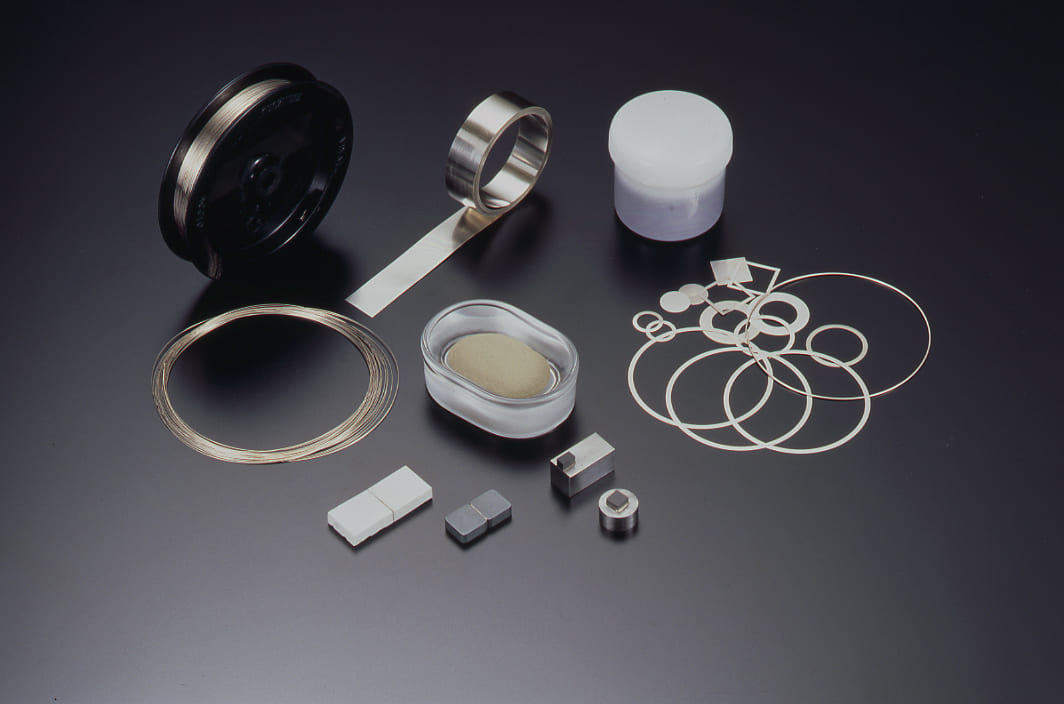
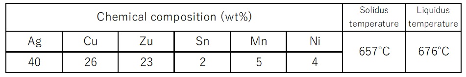
Considering this situation, this team developed an alloy (40Ag-26Cu-23Zn-5Mn-4Ni-2Sn) with equivalent brazing characteristics to BAg-7 (56Ag-22Cu-17Zn-5Sn), but with 40% or lower silver content, a melting point of 700°C or lower, and solidus-liquidus temperature differential of 50°C or lower. With a view to actual commercialization, the developed brazing filler is also provided with good workability for alloy manufacturing to enable processing into wire rod and foil products that general silver brazing alloys are supplied as. Table 1 shows the composition and solidus/liquidus temperatures of the developed brazing filler.
2. Results to date
The basic brazability of the developed brazing filler was evaluated with the base materials brass, carbon steel, and oxygen-free copper.
Wet spread tests identified good wettability with brass, carbon steel, and oxygen-free copper. Compared to BAg-7, the developed brazing filler showed excellent wet spreadability with carbon steel, but slightly poorer wet spreadability with oxygen-free copper and brass.
In the tensile shear test, the filler showed equivalent strength to BAg-7 with brass, carbon steel, and oxygen-free copper. When the base material was carbon steel, all fracture points were the same, with all fracture cracks occurring near the interfaces. When the base material was oxygen-free copper, all fractures occurred in the base material.
Microstructural observation of the joint cross-section showed that good joints were achieved without defects, such as voids or pinholes in the brazing filler layer. When using the developed brazing filler, a copper and zinc compound layer was observed at interface surfaces between all base materials and the brazing filler, which was not observed with BAg-7. It was presumed that the presence or absence of this layer would create a mismatch of strengths at the joint interface with brass. A concentrated layer of nickel, which was thought to be a compound layer of alpha copper (zinc and nickel), was identified at the joint interface with carbon steel. No great difference was seen, between the developed brazing filler and BAg-7, in the brazing filler layer microstructure at the joint interface with oxygen-free copper.
3. Evaluating brazability with cemented carbide
Results to date indicate that the developed brazing filler has good brazability with brass, carbon steel, and oxygen-free copper, and excellent wet spreadability with carbon steel in particular.
On the other hand, because brazing is often used for steel material and cemented carbide in areas such as cutting tools, the developed brazing filler is expected to play a part in these areas as well. Therefore, this report presents an evaluation of brazability in respect to cemented carbide. For this purpose, the developed brazing filler was compared with BAg-24, a brazing filler that is generally widely used when brazing cemented carbide.
3.1 Wet spread testing
Results to date indicate that the developed brazing filler has good brazability with brass, carbon steel, and oxygen-free copper, and excellent wet spreadability with carbon steel in particular.
Wet spread tests were performed to evaluate the wet spreading properties of the developed brazing filler with cemented carbide. ISO K10-equivalent material was used as the base material test piece, with each test piece being a board measuring 40×30×3 mm. Brazing filler material (0.1 g) was placed in the center of the test pieces, an appropriate amount of flux (TB-610) was applied, and a torch was used to heat the test pieces from the opposite side. Heating time was calculated in advance and was derived from the heating parameters required to heat the pieces to 750°C. Figure 1 shows the measured results of heating times in pre-testing. It was found that the temperature of cemented carbide test samples rose to 750°C in 70 seconds. Based on these pre-testing results, test pieces were heated, the wet spread area was measured after the brazing filler was heated and melted, and wet spreadability was evaluated. The developed brazing filler and BAg-24 were used in the testing, and the results were compared.
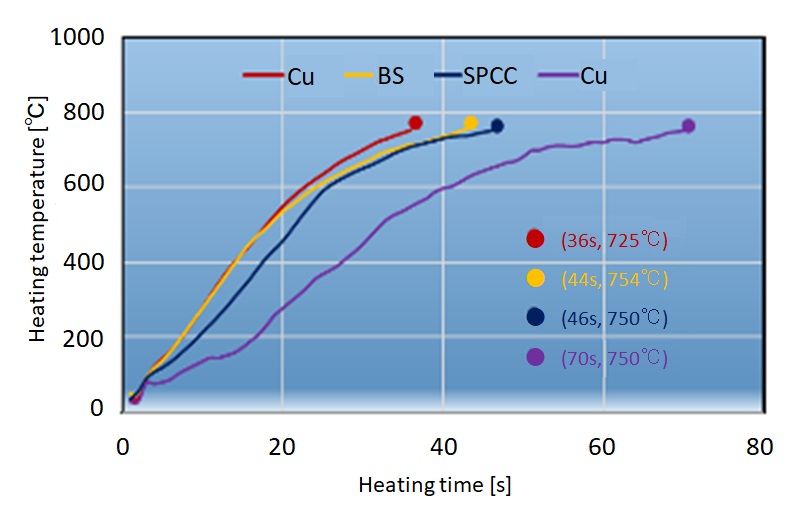
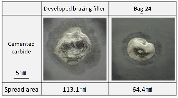
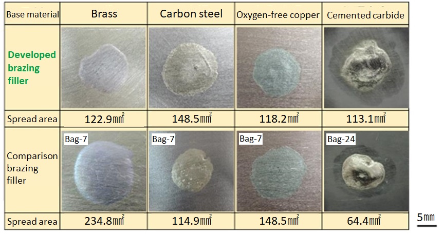
Figure 2 shows the results of the wet spread tests. Compared to BAg-24, the developed brazing filler exhibited better wet spreadability with cemented carbide. However, neither brazing filler demonstrated clean wet spreadability on cemented carbide at 750°C, so the heating temperature may not have been appropriate for this base material. This temperature was used to ensure the same heating parameters as for the previous results from brass, carbon steel, and oxygen-free copper in order to make a comparison. Figure 3 shows the results of all materials. The results of comparing wet spreadability for each base material show that the developed brazing filler exhibited better wet spreadability than the comparison filler with carbon steel and cemented carbide.
Therefore, the developed brazing filler exhibited better brazability than BAg-7 and BAg-24 with iron-based materials and cemented carbide, which suggests it would be effective when brazing in areas such as cutting tools.
3.2 Strength testing
Compression/tension shear strength testing was performed to evaluate the joint strength of the brazing area.
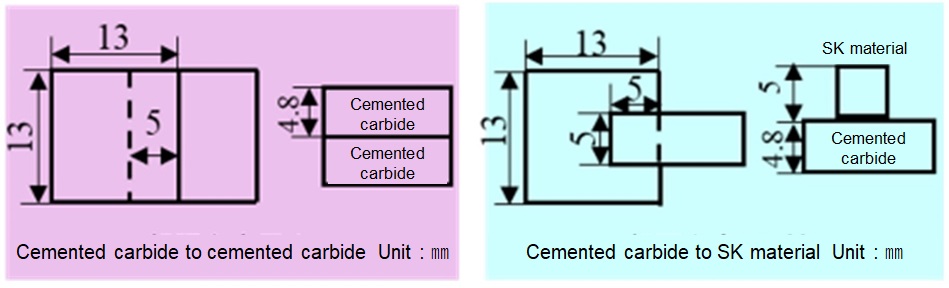
For the base materials, pieces of cemented carbide (K10-equivalent) were joined, and cemented carbide was joined with SK material (SKS3 carbon tool steel-equivalent). Figure 4 shows the shapes of test pieces. It includes joint shapes and overlaps, with the cemented carbide test pieces measuring 3×13×4.8 mm and the SK material test pieces measuring 13×5×5 mm. With zero clearance between surfaces, joint surfaces were temporarily spot welded together to create the test piece joints. A set amount of brazing filler (0.1 g) was placed directly beside the joint surfaces.
Continuous hydrogen furnace brazing was performed in the furnace without flux. Material temperature was measured in advance and brazing was performed at a setting that maintained the test piece temperature at the brazing filler melting point or higher for approximately 12 minutes.
An Instron Universal Testing Machine (INSTRON 2716-015) was used for strength testing, with a cross-head speed of 1.5 mm/min. A total of five test samples were used.
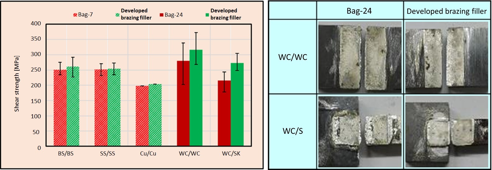
Figure 5 shows the results of shear tests and photographs of the fracture surfaces. Visual observation of the fracture surfaces showed fractures in the brazing layers of all test pieces. No significant voids, pinholes or other visually discernible defects were identified in visual inspections of the brazing layer. When joining pieces of cemented carbide, or cemented carbide and SK material, the developed brazing filler exhibited greater joint strength than BAg-24. Also, the strength of the joint between cemented carbide and SK material was lower than that between the pieces of cemented carbide.
3.3 Microstructural observation and elemental analysis of joint cross-section and fracture surface
The microstructure of the joint cross-section was observed by SEM, and the behavior of each element at the joint interface was analyzed by EDS. Using SEM imagery for microstructural observation of the cross-section, no voids, pinholes or other significant defects were identified in the brazing filler layer between the developed brazing filler and each base material. The developed brazing filler was confirmed to have excellent joint filling properties that produced good joined pieces.
Figure 6 shows SEM imagery of joint interfaces, and the results of EDS-based elemental analysis, when using the developed brazing filler to join the pieces of cemented carbide. Likewise, Figure 7 shows SEM imagery of joint interfaces, and the results of EDS-based elemental analysis, when using BAg-24 to join the pieces of cemented carbide.
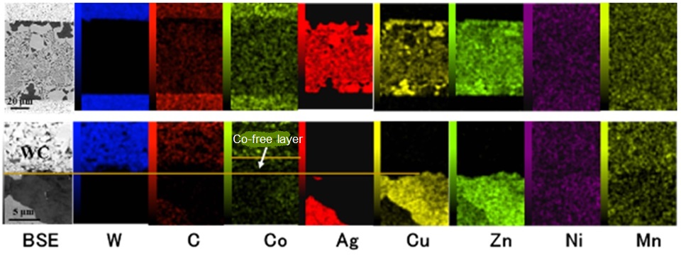
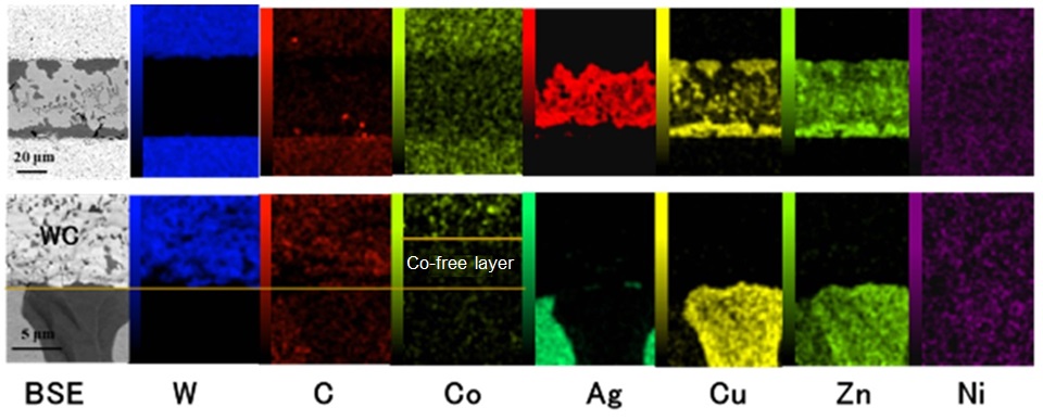
For both brazing fillers, the microstructure observed in the brazing filler layer comprised a mix of silver-based solid solution and copper-based solid solution. Cobalt-free layers were identified in the base materials near the joint interfaces, with the cobalt-free layers being more extensive with BAg-24. Also, nickel and manganese from the brazing filler was observed to be diffused through the base material. This diffusion of nickel and manganese from the brazing filler was thought to have been promoted by the formation of a cobalt-free layer at the joint interface.
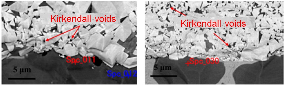
Figure 8 shows SEM imagery of the joint interfaces for the developed brazing filler (left) and BAg-24 (right). Kirkendall voids were identified near the joint interfaces for both brazing fillers, while BAg-24 tended to show a greater number of voids than the developed brazing filler.
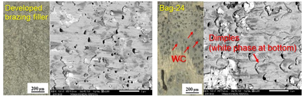
Microstructural observation was performed on the fracture surfaces after shear testing of the joined cemented carbide pieces. Figure 9 shows optical microscope images and SEM images of fracture surfaces for the developed brazing filler and BAg-24. Dimple-shaped fractures were identified in the fracture surface of the developed brazing filler, and white phase was observed as small dots. On the other hand, dimple-shaped fractures were also identified in the fracture surface of BAg-24, and a large and extensive white phase was observed. These white phases were thought to be the base material cemented carbide, and the fractures were found to be occurring near the interface.
From the above results, it was presumed that the failure mechanism was a drop in strength of the cemented carbide itself near the brazing interface, due to the formation of a cobalt-free layer, and that the failure started preferentially at a point where Kirkendall voids were concentrated in the cemented carbide side. In addition, it was thought that dimples formed around minute particles of cemented carbide at the brazing side adjacent to the joint interface, and that cracks propagated along the dimples during ductile fracture of the brazing filler layer. In other words, it was presumed that the strength of joints between pieces of cemented carbide was impacted by the degree to which a cobalt-free layer was formed, and that because the developed brazing filler experienced less of an impact from lack of cobalt, it exhibited greater strength than BAg-24.
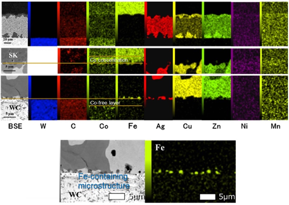
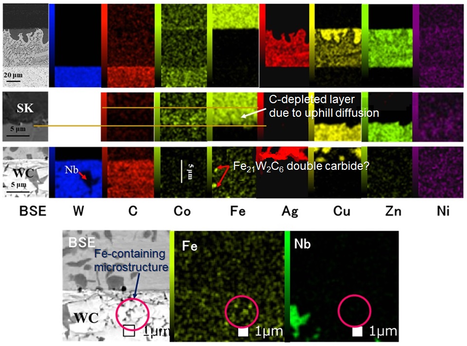
Next were SEM imagery of joint interfaces, and the results of EDS-based elemental analysis, when using the developed brazing filler and BAg-24 to join cemented carbide and SK material. Figure 10 shows SEM imagery of joint interfaces, and the results of EDS-based elemental analysis, when using the developed brazing filler. Likewise, Figure 11 shows SEM imagery of joint interfaces, and results of EDS-based elemental analysis, when using BAg-24.
Like the joints between pieces of cemented carbide, for both brazing fillers, the microstructure observed in the brazing filler layer was comprised of a mix of silver-based solid solution and copper-based solid solution. Roughly the same reaction seen with the pieces of cemented carbide was identified at the joint interface on the cemented carbide side. However, a concentrated layer of iron was formed at the interface on the cemented carbide side when using the developed brazing filler, whereas iron was diffused within the cemented carbide and an iron-rich phase was formed when using BAg-24. On the other hand, a diffusion of cobalt within the base material was observed at the joint interface on the SK material side. A carbon-depleted layer, which was thought to have been caused by the effect of uphill diffusion, was also identified.
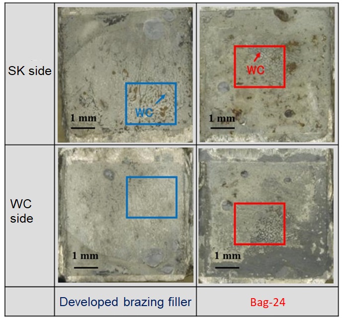
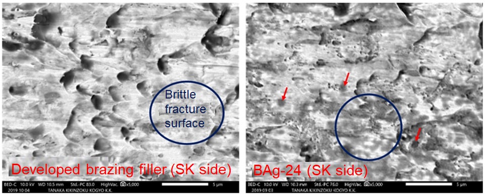
Microstructural observation was performed on the fracture surfaces after shear testing of the joined cemented carbide and SK material. Figure 12 shows optical microscope images of fracture surfaces for the developed brazing filler and BAg-24 with both base materials. During observation of the fracture surface on the SK material side, cemented carbide was identified at part of the surface, and this was thought to be material detached from the base material. This tendency was greater with BAg-24 than with the developed brazing filler.
From the above results, the presumed failure mechanism was that the failure started from a reaction product generated through the diffusion of iron from the SK material to the cemented carbide side. Because the iron was completely diffused through the cemented carbide when using BAg-24, an iron-rich double-carbide phase was formed within the cobalt-free layer. On the other hand, the iron mainly concentrated along the interface of the brazing area when using the developed brazing filler, and the amount of carbide produced in the cemented carbide was less than when using BAg-24. When joining cemented carbide and SK material, it was presumed that joint strength was impacted by the amount of double carbide produced at the joint interface on the cemented carbide side.
4. Summary
This report has presented an evaluation of the brazability of a developed brazing filler in respect to cemented carbide. It also included a comparative evaluation with BAg-24.
The developed brazing filler exhibited good wet spreadability with cemented carbide, and excellent wet spreadability when compared to BAg-24.
It also exhibited greater joint strength than BAg-24 when joining pieces of cemented carbide, or cemented carbide and SK material.
Through analysis of joint cross-sections and observation of the fracture surfaces after shear testing, the failure mechanisms were found to differ between joining pieces of cemented carbide and joining cemented carbide and SK material. The strength of joints between pieces of cemented carbide was impacted by the degree to which a cobalt-free layer was formed, and when joining cemented carbide and SK material, joint strength was impacted by the amount of double carbide produced at the joint interface on the cemented carbide side.
From the above results, the developed brazing filler was found to exhibit excellent brazing characteristics with cemented carbide when compared to BAg-24.
Reference documents
1) “Development of a Low-temperature Cadmium-free Silver Brazing Alloy with Reduced Silver Content,” Kotaro Matsu et al, BRAZE magazine, Volume 54, Issue 125 (2020)
2) “Microstructure and Strength of Interface in Joint of WC-40mass%Co Alloy/Carbon Steel,” Yasuki Miyakoshi, Kohji Takazawa, Kohsuke Tagashira, Shuichi Kamota, Hidenori Takahashi, Journal of the Japan Society of Powder and Powder Metallurgy, Volume 44, Issue 10 (1997)
3) “Brazing of Cemented Carbide Using Ag-based Filler Metals with a Low Melting Point,” Shinji Yaoita, Quarterly Journal of the Japan Welding Society, Volume 29, Issue 3 (2011) pp. 204-209
4) “Effects of Ni and Co Elements in Filler Metals in Ag-brazing of Cemented Carbide,” Shinji Yaoita et al, Quarterly Journal of the Japan Welding Society, Volume 30, Issue 4 (2012) pp. 298-305
5) “Cemented Tungsten Carbide/Carbon Steel Joint Brazed with Copper,” Hirohiko Ohmura, Kouji Kawashiri et al, Quarterly Journal of the Japan Welding Society, Volume 6, Issue 4 (1998)
For inquiries regarding this article, please contact Tokyo Braze Co., Ltd. (info@tokyobraze.co.jp)

